
Concrete Cutters
Where and How Are Concrete Cutters Used?
How the concrete cutter, which works on the cut and crack principle, is actually run in high reach demolition, selective dismantling and on the recycling site.
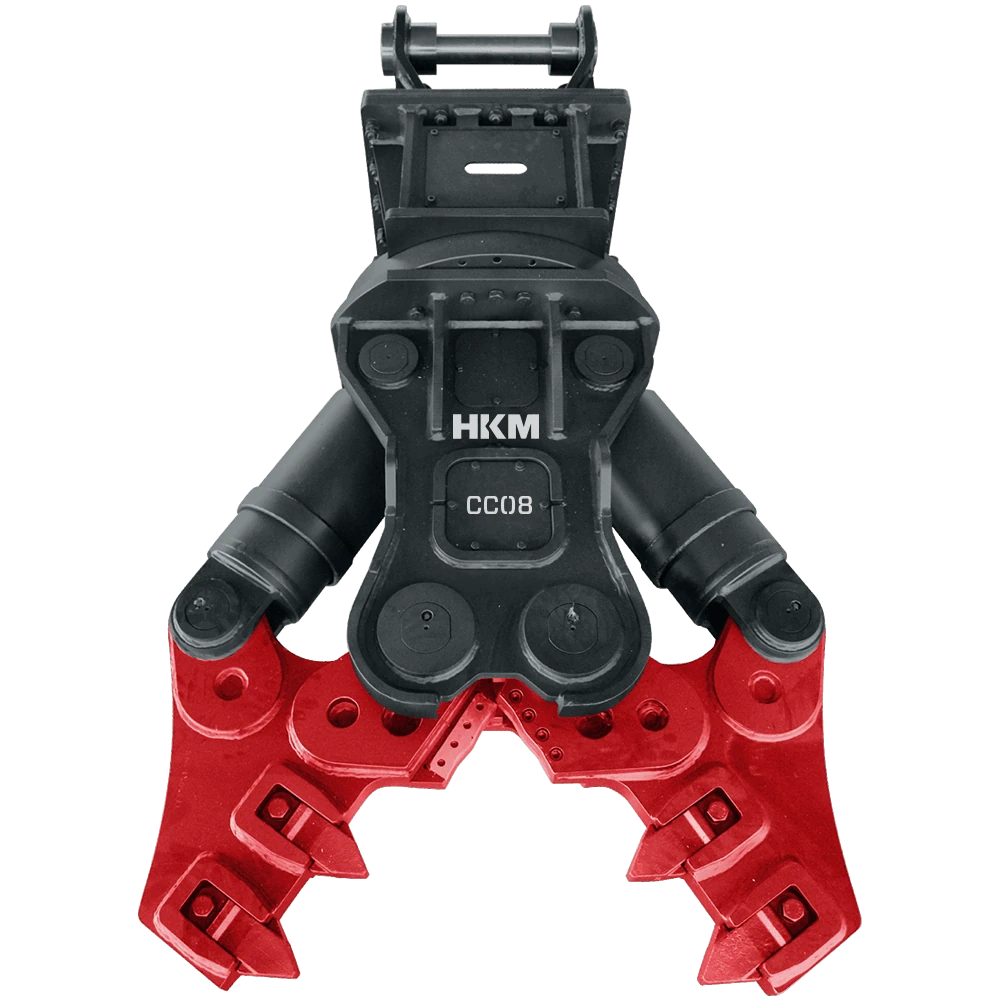
A concrete cutter is a hydraulic attachment fitted to the excavator stick that bites reinforced concrete elements out of the structure with two pointed jaws. The tips first enter the concrete section and crush the contact area; as the jaw keeps closing, tensile stress builds in the remaining section and the element breaks away there. In the industry this way of working is called cut and crack. Thanks to the narrow, deep jaw geometry, elements such as columns, beams, walls and slabs are removed without any impact being applied. The main applications are taking down elements on upper floors and at points the machine cannot approach, demolition with low noise and vibration inside built up areas, selective dismantling next to sections that are to be preserved, and pre-sizing large pieces on the recycling site.
This geometry also determines how the work is set up on site. Because the jaw mouth is narrow, a thick column is not taken in a single move; progress is made with successive bites along the section. In a high reach demolition arrangement with a long boom, attachment weight becomes more decisive the further the reach goes, so the model is chosen together with the carrier's load curve. On rotating head types the jaw enters the element at the right angle without repositioning the carrier, and approaching a beam at height from below is only practical this way.
Below you will first find the working routine on demolition and restoration sites and on the recycling site: the job preparation, the operator's biting sequence and where the output goes. Then we go into the parts of the attachment, operator habits and maintenance decisions. We have also written out the jobs a concrete cutter is not suited to; using the attachment at the wrong stage both stops progress and drives up the consumable bill.
Demolition & Renovation
The biting sequence in high reach demolition and selective dismantling
Preparation starts with deciding the order in which the structure will come down. The structural system is studied; which column carries which beam, and where the load will transfer as elements are removed, is planned in advance. The drop zone is marked and cleared, and the sections to be preserved and the boundary of the adjoining structure are established on site. In a long boom arrangement the attachment weight is compared against the reach curve, the hose run is secured along the boom and the rotating head line is checked. The working direction is chosen so that the pieces breaking away fall in front of the carrier and the machine does not have to climb onto the debris.
On every element the operator looks for the narrowest dimension of the section and sets the tips there. The first contact has to be perpendicular to the face of the section; a tip that comes in at an angle slides on render or cladding. The sequence generally runs from top to bottom and from the secondary elements towards the structural ones: slabs and beams are relieved first and the column is taken last. On thick sections no single move is expected; the jaw is walked along the section and progress is made with successive bites. To steer a column into the direction it should fall, part of the rebar on the opposite side is deliberately left uncut; that part acts as a hinge and the element topples under control. Once the piece has separated the jaw is kept closed and the element is laid flat on the ground.
The output is reinforced concrete pieces that have come down under control with their rebar partly exposed; from this point separation passes to the pulverizer and sizing to the crusher bucket. Where a concrete cutter is the wrong choice is equally clear. Cutting steel structure, heavy sections and pipe is the hydraulic shear's job; even a section that fits the jaw mouth will crack the tips if it is forced into them. Stripping rebar from debris on the ground belongs to the pulverizer, and bringing material down to particle size belongs to the crusher bucket. On work with no geometry to grip, such as solid rock and foundation masses, the hydraulic breaker comes first.
- Plan the removal sequence through the structural system; take the secondary elements first.
- Set the tips on the narrowest dimension of the section, perpendicular to the face.
- Do not expect a single move on a thick section; walk the jaw along it.
- Steer the direction of the break by deliberately leaving rebar on the opposite side.
- Do not release the separated piece; lower it with the jaw kept closed.
Do not take the first bite without a sequence plan
Because a concrete cutter takes elements one by one, how the load travels through the structure depends directly on the operator's decision. A column taken in the wrong order can cause an unplanned collapse. The removal sequence is set in the work plan, not on site.
Recycling
Reducing large pieces to feed size on the recycling site
On the recycling site the concrete cutter's job is to bring incoming reinforced concrete pieces down to a size the next step can grip. Preparation starts with laying out the pile: large pieces are spread in a single layer bearing on the ground, and pieces stacked on top of each other are separated. A piece resting on another slides under the bite and the tips work in air. The floor of the cutting area has to be hard. Whether the pieces contain anchors, steel plate or sections is checked beforehand; those belong to the shear, not to the cutting tips.
The operator bites the piece across the narrow dimension of the section and works along the element, splitting it lengthwise. On long slab and beam strips the work starts at one end and the piece gets one step shorter with every bite, so the parts breaking off fall into a space set aside for them rather than onto the pile. The rebar tying the pieces together is cut with the cutting section in the jaw mouth and the elements come apart. On the rotating head type the jaw is turned rather than the piece; the carrier stays where it is and the piece stays where it lies.
The output is properly sized reinforced concrete pieces that fit the pulverizer's jaw or the feed opening of the crusher bucket. Without this pre-sizing the next line blocks constantly and downtime grows. The concrete cutter does not produce aggregate in this flow: coming down to particle size is the crusher bucket's job, and stripping the rebar fully out of the concrete is the pulverizer's. On a mixed scrap pile the right attachment is again the shear; cutting tips are not designed for sheet and sections.
- Spread large pieces in a single layer, bearing on the ground.
- Bite across the narrow dimension of the section and split the element lengthwise.
- Set aside the space the broken off parts will fall into before starting.
- Cut the rebar tying pieces together with the cutting section in the jaw mouth.
- Set the target size according to the feed opening of the next step.
The next attachment sets the target size
On site pieces are often reduced by eye and more bites are spent than necessary. The target is not for the piece to look neat, but for it to go into the mouth of the next attachment at the first attempt.
The parts of a concrete cutter and what each one does
Performance in a concrete cutter comes not from a single part but from the jaw geometry and the place the force is applied working together. The list below also shows where to look when progress slows.
- Jaw tips and geometry
- The jaws are narrow, deep and pointed. The force is not spread over a wide surface but concentrated at a few contact points, and the tips enter the concrete section. How sharp the tips are decides how easily that entry happens; a dull tip slides across the face instead of entering the section, and the operator notices it on the first bite.
- Cylinder and closing force
- The cylinder that closes the jaw is housed inside the body. The closing force is not constant along the jaw: it rises towards the pivot and falls towards the tip. Thick sections are therefore taken in the root area of the jaw, and thin sections anywhere along the mouth. Force and opening values by model are given in the manual.
- Rebar cutting section
- In the jaw mouth there are blade areas set aside for cutting the rebar that ties the element to the structure. This area is for the bars inside reinforced concrete; it is not designed for heavy sections and plate. When the bolts in its seat work loose the blade starts to eat its own seat, so checking the bolts belongs in the shift routine.
- Rotating head
- On the rotating type the jaw sits on a hydraulic head that turns through three hundred and sixty degrees and is fed from a separate line. Its gain in high reach demolition is obvious: entering a beam from below or a column from the side at the right angle needs no repositioning of the carrier. The rotary coupling inside the head passes the oil through without winding up the hoses through the rotation.
- Body and mounting
- The body carries the load coming from the jaw and the cylinder into the carrier's boom; the adapter, pin diameter and lug spacing are set by the carrier. If a quick coupler is used, its own weight enters the calculation as well. If there is a crack in the body, opening at the weld areas or play in the adapter, work is stopped.
- Wear tips and liners
- The tip teeth and the wear liners inside the jaw are replaceable parts, fitted so that they wear instead of the body. Wear is not spread evenly along the jaw; the area that enters the section first always goes ahead of the rest, so that is the area monitoring is based on.
A dull tip looks like a loss of force
When the element will not break, the first thought is a drop somewhere on the hydraulic side. But in cut and crack the first step is for the tips to enter the section; when a dull tip cannot manage that entry, no amount of force from the jaw will create a line of weakness in the section. Check the profile of the tips before you question the cutting force.
Operator habits: where to bite and how to bring the structure down
Two decisions govern everything with a concrete cutter: where on the element to bite, and in what order the elements are taken. The first directly affects the service life of the attachment, the second the safety of the site.
The bite point is on the narrowest dimension of the section and in the part of the jaw close to the pivot. Biting from the tip means using the place where the force is lowest and concentrating the wear on the tips of the teeth. The first contact has to be perpendicular to the face; on a rendered, clad or sloping surface the tip slides and cannot enter the section. In that case the surface layer is taken off first, or a starting area is opened from the free edge of the element. On thick columns the jaw is walked along the section and progress comes from successive bites.
The sequence plan runs from beams to columns and from the upper floor down. When a column is taken, the side the break will run towards is chosen beforehand and part of the rebar on the opposite side is left as a hinge; the element turns under control on that hinge. The separated piece is lowered with the jaw kept closed and laid flat on the ground. At no stage does the carrier position itself beneath elements that have not yet been taken.
- Do not try to break off an element you have gripped by pulling with the boom or slewing the upper structure.
- Do not bite from the tip; the tip profile breaks down quickly where the force is low.
- Do not use the concrete cutter to cut sections, pipe and plate.
- Do not carry pieces with the jaw; carrying and stacking are the grapple's job.
- Do not release a piece that has broken free; lower it under control even if the drop zone is clear.
- Do not take the machine under elements that have not yet been removed.
Leaving a hinge is a technique; forgetting it is a risk
Leaving part of the rebar uncut to set the direction of the break is a common and correct method. What is wrong is leaving that part without planning it: the element turns towards whichever side the uncut rebar is on. The decision on direction has to be made before the bite.
Maintenance: tip life, the pivot and the hydraulic line
- Monitoring tip wear
- Tips lose their profile before they go blunt; entry into the section gets harder, progress slows and the operator starts spending more bites on the same element. That is the earliest sign that renewal is due. The wear limit up to which the tips can be used is specific to the model and is taken from the manual.
- Hardfacing or replacement
- Worn tip areas can be renewed by welding, but that decision depends on the material of the tips and on where the wear has gone. In hardened areas uncontrolled heat input starts a crack; preheating, electrode selection and the post weld cooling regime follow the manufacturer's instructions. On models with replaceable tips, replacement is usually the economical option rather than welding. Make the decision by consulting the manual or us.
- Pins, bushings and out of line closing
- When the play at the jaw pivot grows, the two jaws no longer meet and the tips enter the section sideways. That both cuts the cutting efficiency and puts a side load on the tips that they were not designed for. Greasing is done with the jaw free; the play is checked with the jaw closed, by looking at the alignment of the tips.
- Protecting the hydraulic line
- A concrete cutter's line works in an area where debris falls and usually on a long boom. The hoses are secured along the boom, slack is left around the rotating head for the rotation, and rubbing marks are checked every shift. On attachment changes the couplings are wiped before they are fitted; dust that gets into the hydraulic system shows its damage weeks later.
- Bolt and connection checks
- Blade seat bolts, adapter connections and wear liner fixings are checked at regular intervals. Tightening torque values are specific to the model and are given in the manual. A connection that has worked loose ruins first its own seat and then the body.
Before you look for the cause of a slowdown in the hydraulics
When progress drops, three things are checked in order: the tip profile, the jaw alignment and the tightness of the mounting bolts. If all three are sound, looking at the hydraulic side makes sense; if they are not, there is nothing on the hydraulic side to find.
Frequently Asked Questions
How is the direction a piece breaks in decided when working with a concrete cutter?
The direction is chosen before the bite. Part of the rebar on the side opposite the direction of the break is left uncut, and the element turns on that part like a hinge. The drop zone is cleared beforehand, the carrier positions itself out of the direction the element will topple in, and the piece is lowered with the jaw kept closed as far as possible.
Why does the jaw slide on a rendered or clad surface?
The tips have to make contact perpendicular to the face in order to enter the section. Render, tile and similar cladding layers crush under the tips and create a sliding surface. The answer is not more force but taking the cladding layer off first, or opening a starting area from the free edge of the element. If the tips are dull, the same symptom appears on a sound surface too.
How is a concrete cutter used when removing a slab?
On a slab the work starts at a free edge and advances in strips. The jaw is set on the edge of the section, the piece is broken away, and a step is taken inwards for the next bite. The area the broken off parts will fall into is cleared beforehand. At no stage does the machine stand on slab that has not yet been cut; the work is always run from a sound point whose load bearing capacity is known.
When the tips are worn, should they be renewed by welding or replaced?
Both are possible and the decision depends on the type of tip. On models with replaceable tips, changing the part is both faster and more predictable. Renewal by welding calls for preheating and electrode selection in hardened areas; a hardfacing deposit applied wrongly starts a crack. Wear limits and welding instructions are specific to the model and should be confirmed from the manual or with us.
Related Applications
Get access to the HKM Dealer Portal
Access pricing, stock availability, spare parts, and technical resources. Apply now to benefit from HKM privileges designed to strengthen your business and operations.