
Hydraulic Shears
Where and How Are Hydraulic Shears Used?
How a cutting routine with a hydraulic shear is actually set up on site, from steel structure dismantling through to the scrap yard.
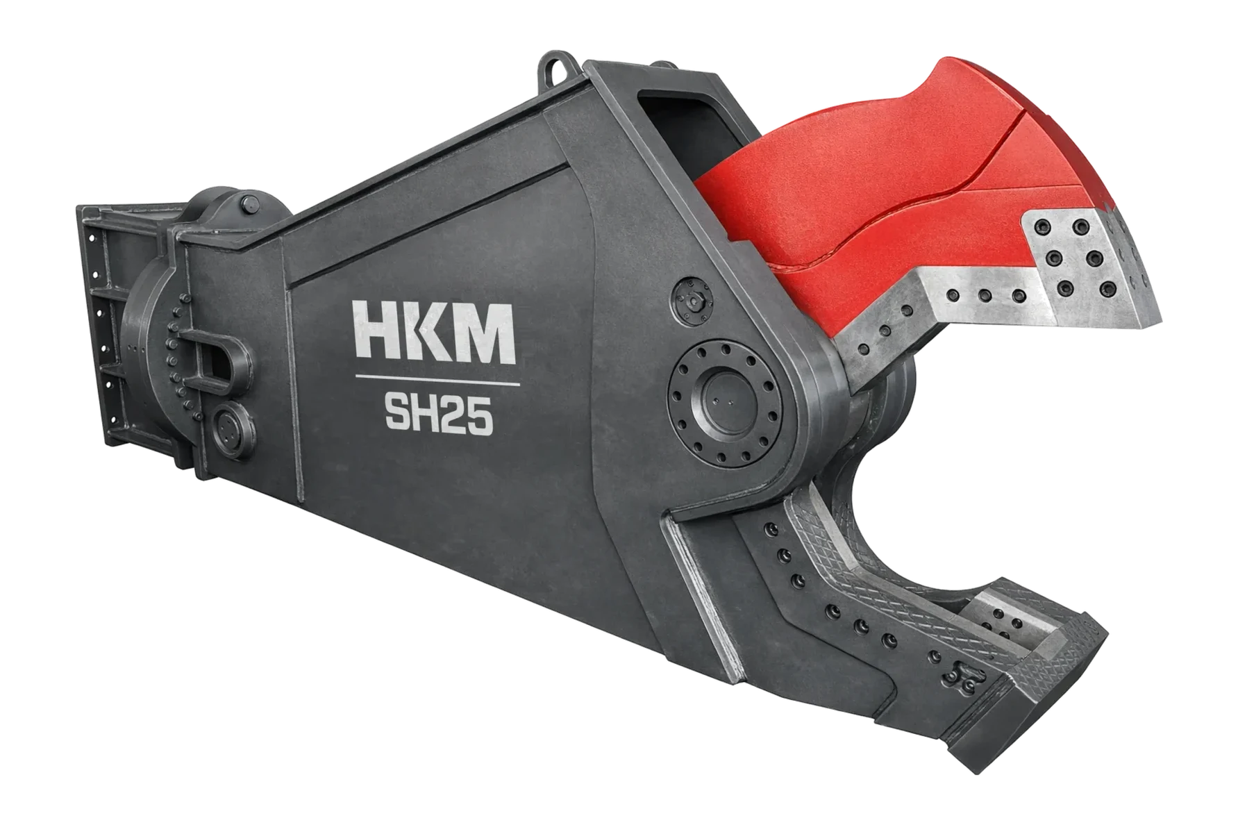
A hydraulic shear is a hydraulic attachment fitted to the excavator stick that cuts metal by shearing it between two blades. The cylinder closes the moving jaw, the blade on it passes right alongside the fixed blade, and the material separates along the cutting line. The process is cold; it produces no flame, sparks or fumes, and the cut is run from the operator's cab. The main applications are dismantling steel structures and industrial plant, cutting pipe and tanks, sizing the rebar and sections exposed during reinforced concrete demolition, and bringing incoming metal down to feed and haulage size in scrap yards.
There are two different set-ups on site and they behave differently. In the demolition set-up the shear works at the end of the boom, inside the structure and in place; here reach, weight balance and cutting sequence are decisive. In the scrap set-up the shear usually works on a material handler, in cycles repeated at the same point; here jaw opening, cycle speed and blade consumption come to the fore. On rotating head types the jaw positions itself through three hundred and sixty degrees, so the carrier does not have to move in order to enter a section at the right angle. In both set-ups the blades are replaceable parts, and they are the shear's real consumable item.
Below you will first find the working routine on demolition and restoration sites and on the recycling site: the job preparation, the operator's cutting sequence and where the output goes. Then we go into the parts of the shear, the decisions taken during the cut and blade maintenance. In every section we have also written out the jobs the shear is not suited to.
Demolition & Renovation
Cutting sequence and control of the structure in steel frame dismantling
In dismantling a steel structure, preparation starts with understanding how the structure stands up. Which element is structural and which is secondary is established; how the frame will weaken as bracing and purlins are removed is planned, and temporary support is put in where necessary. In closed volumes such as pipes, tanks and boilers the contents are emptied and ventilation is provided; although the shear produces no sparks, cutting a volume that holds residues calls for a separate risk assessment. In long boom set-ups the attachment weight is compared against the carrier's reach curve and the hose run is secured along the boom.
The cut is made at the root of the jaw. The force is highest in the area close to the pivot; heavy sections are taken there, while thinner material can be cut anywhere along the jaw. The sequence runs from the secondary elements towards the structural ones: purlins and bracing first, then beams, and columns last. Box and channel sections try to twist during the cut; the section is seated fully inside the jaw and, where necessary, steadied by bearing it against the ground or another element. Cutting an element that is under stress in the middle is the riskiest move: as the section separates the piece can whip and the blade edge can jam. In that case the stress in the element is relieved first and the cut is started from the free end.
The output is metal reduced to a size that can be transported and separated by type; in that state it goes straight to the scrap line. The jobs where the shear is the wrong choice are equally clear. Bringing down a reinforced concrete mass is the job of the concrete cutter and the breaker; forcing the shear into concrete finishes the blade edge quickly. Stripping rebar out of concrete belongs to the pulverizer. On solid sections above the cutting capacity given in the manual the shear cannot make progress and the cutting method is changed. In tight gaps and on selective cuts, flame cutting is still planned as a complementary method.
- Plan the dismantling sequence by working out the direction in which the frame will weaken.
- Cut at the root of the jaw; take heavy sections into the area close to the pivot.
- Seat box and channel sections fully inside the jaw and bear them so they cannot twist.
- Cut an element under stress only after the stress has been relieved, never in the middle.
- Clear the area the cut pieces will fall into before every move.
Do not cut an element under stress in the middle
When a section that is carrying its own weight or holding another element is cut, the stored energy is released all at once: the piece whips as the section separates, the blade edge jams, and the shear is left under load without completing the cut. A cutting routine always starts by relieving the stress.
Recycling
Repeat cutting and sizing routine in the scrap yard
In a scrap yard the shear works at a fixed point, repeating the same movement all day. Preparation is about setting up a layout that makes the repetition productive: the feed pile, the cutting area and the outgoing containers are positioned so that they all stay within a single slewing arc of the machine. Incoming material is separated by type before cutting; springy thin sheet, bundles of rope and wire, solid sections and cast iron pieces all behave differently in the shear. The floor of the cutting area has to be hard, and the cut pieces have to be cleared at intervals rather than allowed to pile up.
The operator grips a long element so that it comes to the root of the jaw rather than at the tip, and shortens the piece step by step along its length. After each cut the remaining part is repositioned for the next one; releasing the piece and gripping it again is both faster than dragging it with the jaw and easier on the blade. On the rotating head type the jaw is turned rather than the section. Bundled materials such as rope and wire are held at the root of the jaw; a bundle spread along the mouth puts an uneven load on the blade and produces bending instead of a cut. Brittle pieces such as cast iron do not cut, they crack; when that behavior is not expected, the blade tip takes the damage.
The output is scrap separated by type that makes efficient use of container and truck volume. The cut size is not arbitrary; it is set both by the dimensions of the transport vehicle and by the size the buyer accepts. Here too the shear is not the answer to everything. A mixed pile containing concrete and stone is not the shear's field; material with concrete in it belongs to the pulverizer and the crusher bucket. On piles of thin sheet, if the blade clearance has opened up, the material bends instead of being cut and the output suffers. Picking material out of mixed waste and moving it is the grapple's job.
- Set the feed, cutting and outgoing points within a single slewing arc.
- Separate incoming material by type before cutting.
- Shorten long elements step by step along their length from the root of the jaw.
- Hold rope and wire bundles at the root of the jaw rather than spread along the mouth.
- Set the cut size according to the transport vehicle and the size the buyer accepts.
Repeating the same movement finishes the blade at one point
In repeat cutting the material comes to the same area of the blade every time, and that area goes dull well before the rest. Shifting the cutting point along the mouth markedly increases the total number of cuts obtained from a set of blades.
The parts of a hydraulic shear and what each one does
The working surface on a shear is the blade, but the quality of the cut is set as much by the arrangement around the blade as by the blade itself. The list below shows where to look when the cut face deteriorates or progress stops.
- Blades and blade seat
- Blades are made from hardened steel and are generally designed with more than one cutting edge; when the edge in use goes dull the blade is taken off and turned round to bring a new edge into service. The blade seat supports the blade against the side force generated during the cut. Play in the seat, or a bolt that has worked loose, leaves the blade unsupported, and that is usually where a crack starts.
- Piercing tip
- The piercing tip at the outer end of the jaw mouth opens the first entry in items such as plate and pipe and draws the material into the jaw. It does not do the cutting; it carries the material to the cutting area. Wear on this tip shows up as gripping getting harder and material escaping from the jaw mouth more often.
- Jaw opening
- The opening decides what section can be taken into the jaw. A wide opening grips large pieces, but because the cutting force falls the further you get from the pivot, the actual cut is still made in the root area. The balance between opening and cycle speed is struck differently in demolition and scrap set-ups; values by model are given in the manual.
- Cylinder
- The cylinder that closes the jaw is protected inside the body. If the blade jams during a cut the load goes straight into it, which is why an unfinished cut calls for opening the jaw and repositioning rather than pulling. If there is scoring on the rod or leakage around the body, work is stopped.
- Rotating head
- On the rotating type the shear positions itself about its own axis and is fed from a separate hydraulic line. Turning the jaw rather than the section keeps the material where it is and reduces the carrier's maneuvering. The rotary coupling in the head passes the oil through without winding up the hoses and is a priority area in maintenance.
- Body reinforcement
- The body carries the reaction force generated during the cut into the end of the boom. The wear plates around the mouth protect the body from the abrasion of the metal. A crack in the body or opening at the weld areas is a structural finding that has to be assessed immediately.
The blade seat is the invisible half of the blade
A significant share of blade cracks comes not from loss of sharpness but from lack of support. A blade with play in its seat, or with a loose bolt, is forced out of its own plane during the cut. When fitting a new blade, the cleanliness and flatness of the seat matter as much as the blade itself.
Operator habits: cut point, sequence and control
When working with a shear, output and blade life are set by the same decision: where in the jaw the material is taken. The cutting force is highest in the area close to the pivot, because the force arm is shortest there; the blade is also best supported in the same area. A heavy section taken at the tip of the mouth is being cut both with low force and with an unsupported part of the blade, and the result is that progress stops and the blade tip cracks. Thin materials can be cut anywhere along the mouth, but even there the cutting point should not be kept in the same place all the time.
The cutting sequence is built around what the material will do after it is cut. Inside a structure the work moves from the secondary elements towards the structural ones, and the area the broken off piece will fall into is cleared before every move. Long elements are shortened step by step starting from the free end. Box sections, channel sections and pipe try to twist during the cut; the way to prevent that is to seat the section fully inside the jaw, bear it against the ground or another element where possible, and close the jaw in one move without hesitation. A cut that is stopped halfway and started again puts an uneven load on the blade edge.
- Do not cut with the tip of the blade; heavy sections are taken to the root of the jaw.
- Do not use the shear as a pulling, lifting or carrying device.
- Do not try to tear the piece off by slewing the carrier before the cut is complete.
- Do not cut an element under stress in the middle.
- Do not try to cut material with concrete in it with the shear.
- Do not turn the rotating head while the jaw is under load.
If the section is twisting, the problem is the grip, not the cut
Box and channel sections turn about their own axis during the cut and escape ahead of the blade. Trying to solve that with force leaves a burred cut face. If the section is not seated fully inside the jaw, if its far face is not bearing on anything, or if it was gripped at the tip of the mouth, twisting is unavoidable; the correction is made at the gripping stage.
Maintenance: blade set, clearance setting and lubrication
- The blade turning sequence
- Because blades are designed with more than one cutting edge, a large part of their service life is gained by turning them. Turning is not done before the edge has genuinely gone dull; turning early wastes usable edge, leaving it late damages the blade body. Blades that work against each other are handled together: turning only one of them destroys the alignment between the two edges.
- Replacement as a set
- Blades are renewed as a matching set, not one at a time. Pairing a new blade with a worn one creates a variable clearance along the cutting line, and the new blade is damaged before long as well. The seat face is cleaned before the blade is fitted; a burr or dirt left behind pushes the blade out of its own plane.
- Blade clearance setting
- The clearance between the moving and the fixed blade is the setting that governs cutting quality, and it is generally corrected with shims. When the clearance opens up, the material starts to bend between the two edges instead of being cut; burring on the cut face increases, progress slows and the blade edge works under a side load. The setting value is specific to the model; it is taken from the manual or from us, and it is rechecked every time a blade is turned.
- The hardfacing decision
- Building up a worn blade edge by welding is not appropriate on every model; on a hardened blade uncontrolled heat input starts a crack. The piercing tip and the guide areas, on the other hand, are generally areas that can be renewed with hardfacing. Preheating, electrode selection and the post weld cooling regime are set by the manufacturer's instructions; the decision should not be made without consulting the manual or us.
- Lubrication and connection checks
- The jaw pivot and the rotating head bearings carry high and variable loads during the cut. Greasing is done with the jaw free; grease applied under load does not reach the working surface of the bearing. Blade bolts, adapter connections and rotating head fixings are checked at regular intervals; tightening torque values are specific to the model. On attachment changes the couplings are wiped before they are fitted.
Put blade turning on record
When no record is kept of which blade is working on which edge, a usable edge is often thrown away on site, or work continues on an edge that went dull long ago. A simple shift record makes the number of cuts obtained from a set of blades measurable.
Frequently Asked Questions
How do I stop the material escaping from the jaw when cutting pipe and box sections?
Closed sections tend to turn about their own axis during the cut. The section is seated fully inside the jaw, its far face is borne against the ground or another element, and the jaw is closed without hesitation. The piercing tip is used to draw the material into the cutting area. With a grip taken at the tip of the mouth, escape is all but inevitable; the material is brought closer to the pivot.
What should I do when a cut stops halfway?
If the blade is left buried in the material, do not pull with the boom; that movement produces tearing rather than cutting, the blade edge takes a side load and the cut face is burred. Open the jaw, grip the material again at a point closer to the pivot and start the cut from the beginning. If the same area keeps stopping halfway, the blade clearance and the condition of the edge are checked.
Is it right to cut a bundle of rebar with a hydraulic shear?
It can be cut, but if the bundle is spread along the jaw mouth the load on the blade is uneven and part of it bends rather than being cut. The bundle is gathered at the root of the jaw and cut in a single layer as far as possible. Heavy sections and thin wire are not cut in the same move; feeding the material separated by type protects both the cut face and the blade.
When are blades turned, and when are they renewed as a set?
Turning is done when the edge in use has genuinely gone dull and the cut has slowed, and blades that work against each other are handled together. When all the edges are used up, or if there is a crack in the blade body, they are renewed as a set; pairing a new blade with a worn one makes the clearance variable. After every turn and every replacement the blade clearance is rechecked.
Related Applications
Get access to the HKM Dealer Portal
Access pricing, stock availability, spare parts, and technical resources. Apply now to benefit from HKM privileges designed to strengthen your business and operations.