
Hydraulic Breakers
Where and How Are Hydraulic Breakers Used?
An application guide that explains, at method level, how an excavator mounted hydraulic breaker is actually run on site across six main applications: from the parts to operator habits, from maintenance to the chains that end in damage.
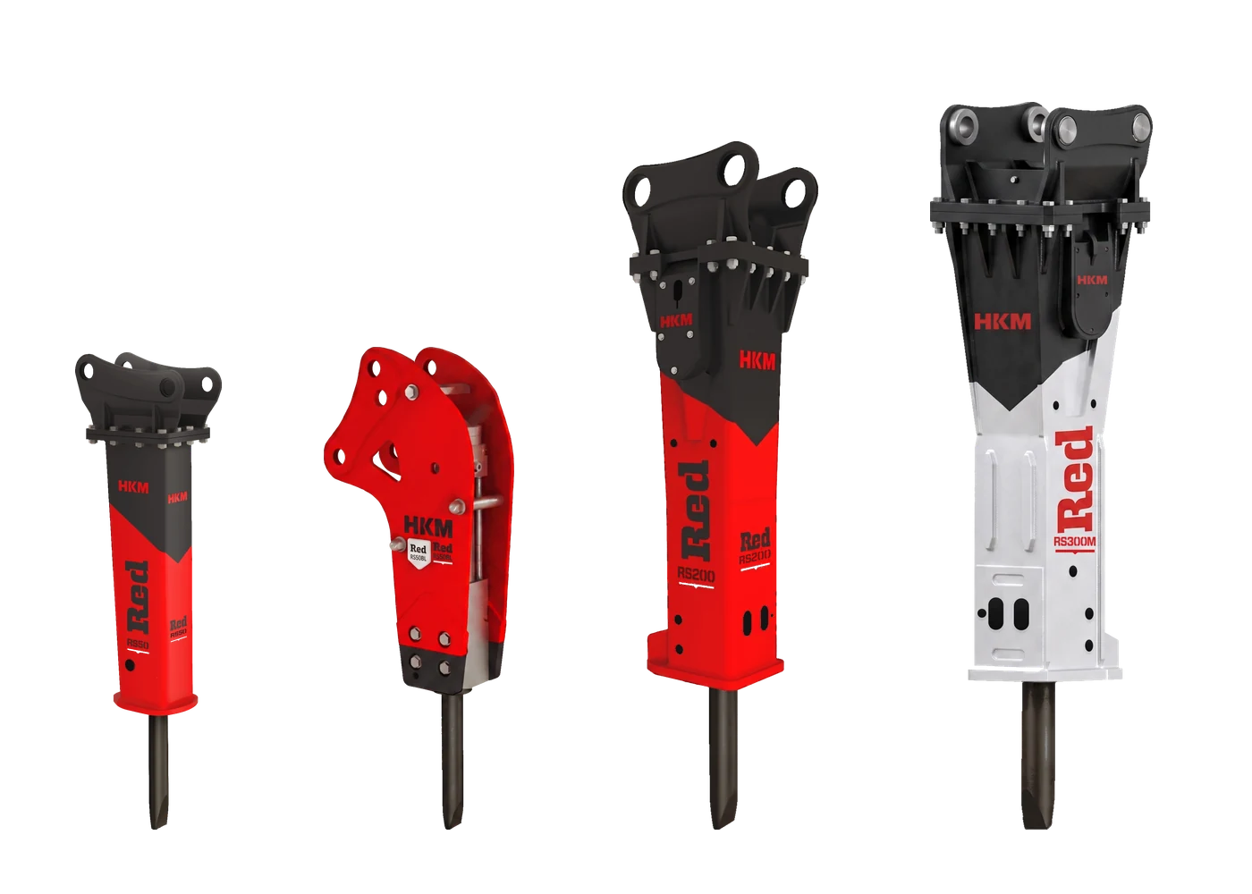
A hydraulic breaker is an attachment connected to the hydraulic line of carriers such as excavators, backhoe loaders and skid steer loaders, and it works through the piston inside its housing striking the tool repeatedly. It uses impact energy to crack hard materials that a bucket cannot remove, such as concrete, reinforced concrete, rock, asphalt and frozen ground, and it breaks them into pieces that can be handled and loaded. Structural demolition and selective removal, reducing boulders in quarries and mines, profile trimming in tunnels, breaking out hard ground and asphalt in infrastructure excavation, clearing rock and stumps on landscaping sites, removing rock in the foundation pit and cropping pile heads are its main applications. On sites where blasting is not possible or depends on a permit, the hydraulic breaker is the most widely used mechanical method of removing hard material.
The working principle is to turn the oil flow coming from the carrier pump into a controlled blow. The oil drives the piston inside the housing backwards; when the stored energy is released, the piston accelerates and strikes the back face of the tool, and the energy travels along the tool into the material as a stress wave, so the material cracks at the point where its own strength is exceeded. Breaking therefore depends as much on where the blow lands and in what pattern as on how hard the blow is. HKM breakers manage this energy in two different arrangements: the Red line works on a fully hydraulic principle, where the accumulator balances the pressure fluctuation of every cycle and keeps the blow steady; the Grey line uses a hybrid arrangement combining gas and hydraulics, and with the support it draws from the gas chamber behind the piston it runs across a wide range of oil flow and pressure. Both lines use the same physics; the difference lies in how the energy is stored and given back.
This page does not stop at the question of where a breaker is used. Below you will first find how the work is actually carried out on site in six main applications: demolition and restoration, mining and quarrying, tunneling and underground, excavation and infrastructure, landscaping and agriculture, foundation work. Then we go into the attachment itself: separate sections cover what each part of the breaker does, the operator habits that decide both output and service life, why maintenance is not a cost item but a production matter, the chains along which damage grows, and the order in which the decisions that raise efficiency are taken. That way you can see on a single page where the output you get from a breaker is won and where it is lost.
Demolition & Renovation
The breaking sequence in reinforced concrete demolition and the limit of selective removal
In demolition, the breaker's work is decided by the plan made before the first blow. The structural system of the building is mapped out: which element carries load, which is infill and in which direction the removal will progress are all settled in advance; the electricity, water and gas lines are cut off, and hazardous material is taken out before demolition starts. In built up areas the permitted working hours, the water used for dust suppression, the vibration that will reach neighboring facades and the area where the debris will fall are part of the same plan. The carrier is set up on a compacted, level platform rather than on the debris pile; the breaker class is selected to suit the carrier and the working height, and the hydraulic lines and the condition of the tool are inspected visually at the start of the shift. The tool type is settled at this stage too: in heavily reinforced, narrow sections a moil point enters the material more easily, while on wide concrete surfaces a chisel tool drives the crack in the direction you want.
The breaker goes to work from a free edge, not from the middle of the mass: an existing void, a window opening or a hole made earlier becomes the starting point, and breaking is driven towards that opening. The operator sets the tool square to the surface and uses the stick to transfer part of the carrier weight onto the tool; with the right feed force the front of the carrier lifts slightly and the blow is transmitted into the material, while with too little feed force the blow bounces back. Side loads that deviate from the tool axis, and prying with the stick, strain the bushings and the tool, so they are used at no stage of a demolition job. On a slab, breaking runs in strips parallel to the supporting beam and towards the direction in which the machine retreats; on columns and beams the breaker only takes off the concrete cover, and the exposed rebar is left to the shear or the pulverizer. On a shear wall the work continues in horizontal strips from the top down; undercutting the base of a standing wall and leaving the upper section hanging creates a risk of uncontrolled collapse.
The output is reinforced concrete brought down to a size the loader and the debris processing line can take; large pieces whose rebar has not been stripped wait on site for a second step. The limit of the breaker shows up most clearly in restoration work: the blow carries the crack beyond the point you strike, so working with a breaker right at the edge of a section that must be preserved leaves unwanted cracks behind. Where the boundary of a section has to be sharp, that boundary is formed first with a concrete cutter or a drum cutter, and the breaker is used only on the mass that remains inside it. Cutting steel structure is the job of the shear and separating concrete from its rebar is the job of the pulverizer; forcing the breaker into that work opens a route that is both slow and expensive.
- The removal sequence and the load bearing elements are identified on the structure before the first blow.
- Breaking always starts from a free edge or an existing opening, never from the middle of the mass.
- The tool rests square to the surface; feed force is applied until part of the carrier weight is transferred onto the tool.
- On columns and beams the concrete cover is taken off and the exposed rebar is handed over to the shear or the pulverizer.
- The boundary of a section to be preserved is formed with a cutter first, and the breaker stays inside that boundary.
Stop the blow the moment you break through
Once the tool has punched through the concrete into open space, carrying on hitting is blank firing: the energy no longer goes into the material but into the breaker's own housing and fasteners. On slabs and walls the moment the section is about to end can be felt from the rate of progress; the instant the tool comes free the blow is stopped and the carrier is moved to a new spot.
Mining & Quarrying
Blast-free breaking at the face, boulder reduction and continuity on the quarry floor
In the quarry the breaker's role falls under two headings: primary breaking on sites where blasting cannot be carried out, and secondary breaking of boulders that will not fit the loading line or the crusher on sites where blasting is used. Before work starts, the bedding and fracture structure of the formation is read; in bedded, fractured rock the breaker moves quickly by opening the weak planes, while the same job slows down noticeably in massive, homogeneous rock. Tool selection follows directly from that reading: in fractured formations of medium hardness a moil point penetrates the material and drives the crack, while in hard, tough rock a blunt tool transmits the energy through a wide contact area and does not go dull early. The carrier is set up on level, firm ground on the bench, the height of the face is compared with the reach of the boom, and loose material above the slope is cleared before work begins.
In primary breaking the work always runs towards a free face: it starts at the top edge of the bench, room is left in front of the broken material for it to move into, and progress is taken downwards in strips. If no crack forms shortly after the tool has entered the rock, the position is changed rather than persisting on the same spot; a breaker is not a drill, it removes material by cracking it, not by crushing it. In boulder breaking the block is first moved onto firm ground, because a block sitting on a cushion of loose debris absorbs part of the impact energy and the job drags on. The impact point is chosen near an edge or along the continuation of a visible crack, not at the exact center of the block; as soon as the block starts to split under its own weight, the blow is stopped. In overburden stripping the breaker is used only on the hard bands; in weathered, bedded overburden a ripper strips faster, and the breaker is kept for its real job, the hard sections that have to be opened.
The output is material brought down to a size the loading and crushing line will accept; because boulder breaking clears a blocked line, the breaker's contribution is usually measured not by the tonnage it produces but by the waiting time it prevents. What decides continuity on the quarry floor is maintenance: in a dusty, abrasive environment the greasing intervals get shorter, grease is applied with the tool pressed up against the breaker, and bushing clearance and tool wear are monitored regularly. On a hot, dusty site the hydraulic oil temperature and the filter condition also go onto the shift check list. The limit has to be stated plainly: on sites that hold a blasting permit and run high volume continuous production, the breaker complements blasting rather than replacing it; and when material has to be produced at a particular grain size, sizing belongs to the crusher bucket.
- The bedding and fracture structure of the formation is read, and the tool type is chosen from that reading.
- Primary breaking is driven in strips from the top edge of the bench towards the free face.
- The boulder is moved onto firm ground; the blow is placed near an edge or along the continuation of an existing crack.
- In overburden stripping the weathered layers are left to the ripper and the breaker is used on the hard bands.
- In dusty conditions the greasing interval is shortened, and grease is applied while the tool is pressed against the breaker.
Hitting one spot does not get you forward
The most common habit on site is to work the same spot for longer when the rock will not break. In material that does not break, the impact energy turns into heat instead of work; the tool anneals, goes dull quickly and the bushings are strained. If short attempts bring no result, the tool is moved to a new spot, preferably one closer to a free face.
Tunneling & Underground
Face advance, profile trimming and invert work underground
Underground, preparation is about the environment itself before it is about the choice of equipment. Ventilation capacity, the exhaust arrangement of the carrier and the water available for dust suppression directly limit how many machines can work inside the section at once; even though a breaker reduces the gas and shock load compared with blasting, managing dust and noise stays at the center of the plan in a confined space. Machine dimensions are assessed together with the section: the length of the breaker, the height the boom can reach and the tail swing of the carrier are the three dimensions that decide positioning in a narrow section. Before anyone moves in front of the face, loose pieces on the roof and the side walls are scaled down, the cab guard and the lighting are checked, and the hydraulic hoses are routed so that they cannot rub against the wall or a rock projection.
Advance at the face starts where two free faces meet: working from a corner, or from the edge of an opening made earlier, gives a far quicker result than hitting the middle of a face that has only one free surface. The operator takes the face in stages, pulls the broken material forward at each stage and repositions the carrier so that the tool axis stays square to the material; as the section narrows, the right approach is to move the machine rather than to force an angle out of the boom. In profile trimming it is never forgotten that the blow carries the crack beyond the point of contact: the breaker is not taken all the way down to the design line, a thin allowance is left and the last layer is removed by a more controlled method. In invert work the high spots are broken first and the loosened material is then cleared without exception; carrying on over loose pieces both absorbs the blow and leaves an invert that looks level but has not settled.
The output of this flow is material broken to a size the haulage equipment can take, and a section ready for support. Another limit on the breaker in a confined space is heat: the air in a narrow section is hot, the cooler of the carrier works with dusty air, and uninterrupted hammering pulls the hydraulic oil temperature up. In a long tunnel and in massive hard rock it is wrong to rely on the breaker alone for full face advance; in those conditions mechanical excavation machines or drilling and blasting become the main method, and the breaker comes in for boulder reduction, profile and invert work. For finishing work that calls for low vibration and an even surface a drum cutter is the better choice; the value of the breaker lies in opening the section, the value of the cutter in finishing it.
- Ventilation, dust suppression and the exhaust arrangement are set up around the machine plan inside the section.
- Breaker length, boom reach and tail swing are assessed together with the dimensions of the section.
- The face is taken in stages, starting at the corner where two free faces meet.
- The breaker is not taken down to the design profile; a thin allowance is left and the last layer is removed by a controlled method.
- Invert leveling does not continue until the broken material has been cleared.
In a confined section, oil temperature is the silent limit
Underground a breaker usually slows down not because it lacks power but because it is running hot. Cooling efficiency drops in a narrow, dusty section; uninterrupted hammering heats the hydraulic oil, the film thickness of hot oil falls and wear accelerates. Building short idle intervals into the shift plan comes far cheaper than the repair that follows otherwise.
Earth-Moving & Infrastructure
Pavement removal, rock and frozen ground along the trench route
In infrastructure excavation, preparation starts with knowing what lies under the route. Records of the existing utilities are collected, the route is marked out, and at critical crossings the real level of the line is confirmed with trial pits dug by hand; the line on the drawing and the pipe on site are often not in the same place. If asphalt or concrete pavement is to be removed, the trench boundary is saw cut first, because in uncut pavement the breaker carries the crack outside the trench line and enlarges the surface that will have to be repaired later. On a route under traffic, closing off the work area, keeping broken pieces from flying onto the road and safety at the trench edge are part of the same preparation; the breaker class is also chosen to suit the trench width and the working angle of the carrier.
In pavement removal the breaker starts at the cut edge and works in strips; each strip is broken towards the free face opened by the one before it. On a rocky route the trench is not taken down to the target depth in one go but opened in layers along the trench axis: the tool is held close to vertical, the carrier works backwards along the line, and the material broken on each pass is lifted out with the bucket. As soon as you come close to a known utility, the method changes completely; work with the breaker stops at the specified cover thickness and the remaining section is opened with the bucket or by hand. In frozen ground the most productive route is not to shave the surface but to break in a grid pattern so that the frozen layer is divided into blocks; thanks to the free faces this creates, the blocks lift out easily with the bucket. In cold weather you wait for the hydraulic oil to warm up before running the machine at full power, because going straight to full impact on cold oil is one of the best known causes of breaker damage.
The material coming out along the route consists of broken rock and removed pavement pieces, and where the specification allows it is sized and then used as fill. The stretches where the breaker is not the right choice also vary along the line: in soft, loose ground the bucket is already enough, in bedded and weathered rock a ripper strips faster, and where the trench wall has to be narrow and even a drum cutter gives a cleaner profile. In sections very close to structures, where vibration is monitored, sawing or static splitting methods are considered. Where the breaker is strong is clear enough: the stretches where the hard layer blocking the excavation, the pavement and the rock bands have to be opened quickly.
- Existing utilities are confirmed with a trial pit; the marking out rests on the site, not only on the drawing.
- On asphalt and concrete pavement the trench boundary is saw cut first, and breaking starts at the cut edge.
- The trench is deepened in layers along its axis, and the broken material is lifted out on every pass.
- When the specified cover thickness is reached the breaker is stopped and the rest is opened with the bucket or by hand.
- Frozen ground is broken in a grid pattern into blocks, and the blocks are lifted out with the bucket.
Vibration reaches the pipe without touching it
When you work near an existing utility, the danger is not only the tool making contact. In hard, continuous ground the vibration of the blow spreads through the surroundings; pipes made of brittle material such as old cast iron or asbestos cement can crack with no contact at all. At critical crossings the breaker is worked alongside the line rather than over it, and the distance is kept.
Landscaping, Agriculture & Forestry
Rock outcrops, old concrete foundations and sensitive surroundings in land clearing
In landscaping, agricultural and forestry work the breaker usually runs on a mini or medium class carrier, in an area with sensitive surroundings. Preparation is built on those two constraints: on a small carrier the weight of the attachment limits the working reach, so instead of stretching far out with the boom extended, you bring the machine closer to the target. Irrigation lines, drainage pipes, power supply cables and tree roots to be preserved are marked out on site; if the route the machine will travel needs ground protection, the material to be laid under the tracks is prepared in advance. Near dwellings, greenhouses or animal shelters the working hours and dust suppression are agreed beforehand; a breaker is a noisy piece of equipment, and it earns acceptance in such surroundings through planning.
On a rock outcrop the work starts at its free edges: taking pieces off the edge instead of hitting the middle of the surface is both quicker and easier on the breaker. The broken material is cleared with the bucket at regular intervals, because carrying on over a cushion of loose pieces absorbs part of the blow and brings progress to a halt. On old concrete foundations a starting opening is made at one edge first, and the slab or the wall is then broken in strips towards that opening; when mesh reinforcement is exposed, the concrete is stripped away and cutting the steel is left to equipment other than the breaker. In land clearing the aim is not to clean the surface completely but to break out the sections that block the working depth you need; the broken rock is taken off the site rather than left in place and covered over, because sharp pieces damage both the equipment and the roots in later soil work.
The output of this work is an area made ready for planting, leveling or building; the broken concrete and rock can be used for a site road or as fill where the specification does not stand in the way. There is work the breaker does not do here either: pulling tree roots and stumps is not a job for a breaker, that work is carried out with a grapple and a ripper. Where a thin rock layer covers a wide area a ripper gets there faster, and in soft ground the bucket is already enough. If the material coming out has to be brought down to a usable size on site, sizing is left to the crusher bucket; the breaker opens the hard section, it does not produce material.
- Irrigation, drainage and power lines and the roots to be preserved are marked out before work starts.
- On a small class carrier the machine is brought closer to the target instead of reaching out with the boom extended.
- A rock outcrop is taken from its free edges; work does not start in the middle of the surface.
- The broken material is cleared at regular intervals; work does not continue over a loose cushion.
- On an old foundation a starting opening is made at an edge, and breaking is driven towards that opening.
Do not try to lever rock out with the tool
The most common mistake on small carriers is to free a loosened piece of rock by driving the tool into a crack and lifting with the boom. Prying is not a load that the tool and the bushings are designed to carry; the tool bends or breaks and the bushing clearance grows quickly. A loosened piece is lifted out with the bucket, and the breaker is used only for blows delivered along its own axis.
Foundation Works
Rock at foundation level, old foundation removal and work around pile heads
In foundation excavation the work of the breaker is tied to a level, which is why the first step in preparation is to mark the design level visibly on site and to set the level the breaker will go down to somewhat above it. The second step is reading the surroundings: the adjoining building, the shoring wall, the anchor line and any existing foundations are assessed; on sites where vibration is monitored, the measuring setup is in place before the breaker starts work. If water collects in the excavation, drainage is sorted out, because on a base standing under water it becomes hard to tell broken ground from sound rock. The platform the carrier stands on must be firm and level; standing close to the excavation edge is assessed separately for both tipping and slope stability.
The rock at foundation level is taken in strips starting from the free face at the excavation edge, and every strip leaves a new free face for the next one; the tool is held close to vertical, part of the carrier weight is transferred onto it, and the broken material is cleared before it builds up. In old foundation removal the element is understood first: whether the foundation to be removed still carries a structure, whether it is retaining ground and whether it is shared with the adjoining plot are all checked; removal starts at the edge of the foundation and works towards its body. Around a pile head the role of the breaker is limited, and that limit is set deliberately: the excess concrete above the cut off level is taken away with the breaker, and the equipment is changed as the cut off line is approached. The tool is not worked resting against the reinforcement cage or parallel to the pile shaft; the concrete is broken away outwards from the shaft, and the exposed rebar is left clean and undamaged for the connection that follows. In sections close to an adjoining building the working direction is chosen away from the structure, the hammering periods are kept short and the position is changed often.
The output is an excavation base whose bearing capacity has not been disturbed, ready for the blinding concrete or the foundation reinforcement that will come on top of it. Where the breaker is not the right tool is especially clear in this work: pile head concrete just above the cut off level, excavations between adjoining buildings that carry a vibration limit, and wall openings that need a clean edge are not left to the breaker; a concrete cutter, a pulverizer or dedicated pile head cropping equipment is used for those. In soft ground that will not stand up on its own there is nothing for a breaker to do, and in bedded, weathered rock a ripper advances faster. In foundation excavation the breaker is the equipment that opens the hard sections; it is not the equipment that forms the finished surface.
- The design level is marked out, and the level the breaker will go down to is set so that an allowance is left above it.
- The adjoining building, the shoring wall and the anchor line are assessed before work starts, and vibration is monitored where needed.
- The rock is taken in strips, starting from the free face at the excavation edge.
- Whether an old foundation still carries load is confirmed before removal begins.
- At the pile head the breaker is set aside as the cut off line is approached, and the job is completed with other equipment.
Overbreak below level cannot be filled back
Breaking that goes below the target level at the foundation base is not made good with compacted fill; the loosened section is cleaned out and filled with whatever the design calls for, usually blinding concrete. That is why the breaker is not taken all the way down to the final level: an allowance is left, the remaining section is removed with the bucket or by a controlled method, and the base is handed over on undisturbed rock.
The parts that make up a breaker and what each one does
From the outside a hydraulic breaker looks like a single mass, but inside it an interdependent mechanism is at work. The oil arriving from the carrier does not turn into a blow directly; it is first directed by a control element, it accelerates a mass, and the energy passes into the material when that mass strikes the shank of the tool. Every link in the chain sits where it can spoil the work of the link before it; knowing the breaker part by part is the shortest route from a symptom you see on site to the right cause.
It helps to think of the parts in three groups. The internal components that produce and manage the energy: the piston, the cylinder, the control valve, the gas chamber and the accumulator. The structural parts that hold them together: the front head, the tie rods, the housing and the wear plates. The contact parts that are sacrificed as they wear: the bushings, the retaining pin, the seals and the tool. Failure usually starts in the third group, and if it goes unnoticed it ends in the first.
- Power cell and outer housing
- The power cell is the internal unit that produces the energy; the cylinder, the piston, the valve and the gas chamber work as a single whole. The outer housing protects that unit from dust and external impact, and on silenced type housings it damps the noise as well. When the housing is dented, the internal unit moves about inside it and the damage builds up on the wear plate surfaces.
- Piston
- The piston is the moving mass that converts hydraulic energy into kinetic energy; it accelerates on every cycle and produces the blow by striking the shank of the tool. The hardness, the finish and the diameter of its working surface decide both impact efficiency and seal life. A scored piston leaks internally, and the oil heated by that leak ages the seals.
- Cylinder
- The cylinder is the main body the piston runs inside; its bore keeps the piston on axis and carries the pressure without letting it escape. The very small clearance between the honed bore and the piston is where the oil film forms; when that film is broken, metal to metal contact begins. Damage to the bore is one of the most expensive repair items, because it has to be dealt with together with the piston and the seals.
- Control valve
- The control valve sets up the impact cycle by directing oil in turn to the forward and rear faces of the piston; the timing of this element sets the rhythm of the breaker. Because the tolerance between the body and the spool is extremely tight, it is one of the parts most sensitive to contamination. A sticking valve shows itself as an irregular blow and as unexpected heating.
- Accumulator and diaphragm
- The accumulator is a pressurized chamber on the high pressure line that stores oil energy and gives it back at the moment of impact; by damping the pressure peaks it also protects the carrier pump. The diaphragm is the flexible membrane that separates gas from oil, and depending on the design it sits inside the accumulator or at the boundary of the gas region. When the membrane tears, the breaker hits weakly and the hydraulics of the carrier are left under an undamped load.
- Nitrogen chamber (back head)
- The nitrogen chamber in the back head is the gas spring that returns the piston and adds force to the blow; a large share of the striking power comes from here. Gas pressure falls naturally over time, which is why measuring it is a scheduled check rather than a repair task. The correct charging pressure is specific to the model and is stated in your manual; when the value for another model is applied, the breaker either hits weakly or is overstrained.
- Tie rods
- The tie rods clamp the back head, the cylinder and the front head together under preload, so that the three parts behave as one body. Because they stretch and relax with every blow, a torque check is an indispensable item of periodic maintenance. When one of them loosens, micro movement begins at the joints, and the chain usually ends with a broken tie rod.
- Front head
- The front head is the structural part that carries the tool and its guide bushings and takes the lateral and bending loads that come in. Using the breaker as a lever, prying and forcing it sideways all land directly on this part. Once the bushing bores go oval or a crack starts, repair usually means replacing the part; this is where the bill for operator habits becomes visible.
- Lower and upper bushings
- The bushings hold the tool on axis inside the front head and take the lateral loads; they are sacrificial parts and their wear is planned for. As the clearance grows, the tool runs off axis with every blow, part of the piston energy does not reach the right place and the seals are loaded unevenly. The acceptable clearance and the wear limit vary by model; take the values from your manual or from us.
- Thrust bushing and wear plates
- The thrust bushing takes the recoil loads coming from the tool and so protects the retaining pin area and the housing, while the wear plates take the lateral load between the internal unit and the housing. Both wear out of sight, and when they are not replaced in time the load is passed on to parts far more expensive than they are.
- Retaining pin and lock pin
- The retaining pin holds the tool inside the front head and limits its axial movement, and the lock pin stops the retaining pin from working its way out. A worn retaining pin lets the tool move about, and a moving tool peens the retaining pin bore; the job ends up at a point where neither the pin nor the tool can be removed.
- Seal kit
- The seals and the o-rings are the thin boundary that separates high pressure oil from the gas region and from the outside. An ageing seal first weeps and then leaks; a leak is not only a loss of oil, it also means dirt coming in by the same route. Renewing the seals as a complete kit prevents a second strip down soon afterwards.
- Hoses, fittings and line components
- The breaker circuit is the most demanding hydraulic line on the carrier: the pressure fluctuates, the temperature is high and the vibration is constant. A hose of the wrong size or a worn hose chokes the flow and causes heating; a loose fitting is a door for both leakage and air ingestion. Fittings left open during removal are the most common way for dirt to get in, and the lines must be capped the moment they are disconnected.
- Tool
- The tool is the last link, where the energy passes into the material, and it is the true wear part of the breaker; it is selected not by how hard the material is but by how it breaks. Its diameter must match the bushing bore; an undersized tool works loose in the bore, and a tool that has been machined afterwards seizes. Peening at the head of the shank is almost always the result of the working method, not of the material.
Parts do not fail one at a time, they fail in a chain
Most of the jobs that start on site with a worn out bushing or a leaking seal are not a single part event. The worn bushing lets the tool run off axis, the off axis tool loads the seal unevenly, the damaged seal leaks, and the dirt entering through the leak scores the piston. If nobody looks at the head of the chain, the same failure comes back.
The same breaker, two operators: the habits that decide output
Two breakers of the same model can deliver very different service lives and outputs even when they work on the same site and in the same material; most of that difference comes from the cab rather than from the equipment. A breaker is not a tool that does its work by force the way a bucket does; it sends energy in as a blow, and for that energy to pass into the material the tool has to be seated correctly. The real job of the operator is to keep that contact condition right throughout the shift.
The basic rule is feed force: part of the carrier weight must be transferred to the ground through the tool, with the help of the boom and the stick. With too little feed force the tool separates from the material and some of the energy is absorbed inside the breaker itself. With too much feed force the front of the machine lifts more than it should, the carrier rides on top of the breaker and the recoil travels straight into the boom and the stick. The sign of the right setting is simple: the breaker runs at a steady, solid rhythm and the carrier does not shake.
- Setting the feed force correctly
- Feed force is the condition that lets the blow pass into the material. With too little, the blow is wasted and the housing vibrates; with too much, the recoil rides onto the carrier and the boom and stick joints are fatigued. The most practical way to find the setting is to listen to the rhythm.
- Keeping the tool square to the surface
- Energy reaches the material only if it travels along the axis of the tool. When the tool is seated at an angle to the surface, a component of the blow turns into a lateral force, and that force is carried by the bushings, the front head and the tool. Working at an angle slows progress, accelerates bushing wear and creates the risk of the tool slipping.
- Avoiding blank firing
- If the blow is not stopped the moment the material breaks, the piston strikes the shank of an unresisted tool with its full energy. That energy has nowhere to go; it builds up as peening at the head of the tool, as impact marks in the retaining pin bore and as loosening tie rods in the housing. It is the fastest damage that can be done to a breaker, and it is entirely under the operator's control.
- Giving up prying and levering
- Lifting or turning a piece with the breaker, or driving the tool into a crack and prying, is a common but destructive habit. The tool and the front head are not designed for bending loads; this use bends the tool, ovalizes the bushing bore and starts a chain that runs as far as a cracked housing. If a piece has to be moved, the right attachment is a bucket, a grapple or a ripper.
- Not persisting on the same spot
- If the material does not crack within a short time, the problem is usually position rather than power. Persisting on the same spot pulverizes the material instead of breaking it and builds up friction heat between the tool and the bushing. The right response is to stop the blow and move the tool a short distance.
- Working from a free face and from the edge
- Breaking happens when the material has an empty direction to expand into. Hitting the exact middle of a large mass traps the energy; working from the edge of the same mass towards a free face takes the piece off with far less energy. An experienced operator creates a free face first and then works inwards from there.
- Reading the material and changing position
- Rock and concrete are not homogeneous; bedding planes, cracks, rebar and voids decide where breaking will start. The sound of the breaker and the rate of progress tell you what the material is doing at that point. A good operator reads that message and moves the tool to the weak plane; an inexperienced one tries spending longer on the same spot.
- Rotating the tool regularly
- A tool does not wear evenly around its body; when it is always worked on the same face, one side flattens and its contact with the bushing is spoiled. Refitting the tool turned about its axis during maintenance or a tool change spreads the wear around; it is a habit that costs nothing extra and pays back well.
- Working underwater and in wet conditions
- Underwater work is not something every breaker can do; a compressed air supply and a configuration to suit it are needed to keep water out of the housing. Worked without the right equipment, water mixes into the oil and the seals and the internal surfaces deteriorate quickly. Confirm from the manual whether your breaker is suitable for underwater work.
- Working in dusty and confined conditions
- On a dry site the real threat is invisible: when dust gets between the bushing and the tool it behaves like an abrasive paste and destroys the grease film. In these conditions the greasing frequency goes up; suppressing dust with water and using a dust channel tool where needed is credited directly to bushing life.
A breaker works by being pressed down, not by being ridden on
The misunderstanding we meet most often is the idea that the power of the breaker grows with the feed force of the carrier. The impact energy comes from the hydraulic system; the feed force only provides the contact that this energy needs in order to pass into the material. Riding the machine onto the breaker does not strengthen the blow, it transfers the recoil into the boom and the stick.
Why maintenance is a direct part of your output
On most sites maintenance is talked about as a cost item; on a breaker, though, what maintenance buys is seen directly in the output. A breaker whose gas pressure has dropped carries on working, but it finishes the same job in a longer time. A breaker with worn bushings carries on striking, but it spends part of its energy on a tool that has wandered off axis. Neglected maintenance appears first as slowing down rather than as a failure, and the bill is paid without anyone noticing.
The second function of maintenance is to cut the chains early. Almost every expensive failure starts months earlier with a cheap symptom: a thin film of oil weeping at a joint, grease that no longer comes out past the bushing, a rhythm that has thinned out, cracked paint around a nut. A visual check of a few minutes before the shift is usually enough to catch these signs.
The items below are deliberately kept at the level of method. Values such as the greasing frequency, the charging pressure, the tie rod torque and the bushing wear limit change from model to model, and giving them as a general figure would be wrong. Take the values from the operating manual of your breaker, and if you do not have the manual, contact us with your model code.
- Grease is applied with the tool pressed against the material or the ground. With the tool hanging free, grease pushed into the gap that opens between the bushing and the tool escapes straight out instead of spreading.
- Too little grease and too much both do harm. Insufficient grease leads to metal to metal contact in the bushing; excess grease strains the seal, and the surplus can pass into the impact area and mix with the hydraulic oil.
- Breaker grease and general purpose excavator grease are not the same thing. Under the temperature and the impact at the bushing, general grease cannot hold its film; the correct grease type is described in the manual of your breaker.
- Hydraulic oil cleanliness is not a single maintenance item but the shared cause behind many failures. Fittings left open during a tool change, a blocked tank breather and manufacturing residue left inside new hoses are the most common ways in.
- A filter change is both a calendar task and a chance to observe. If metal particles are visible in the filter you have removed, fitting a new filter does not solve the problem, it only postpones it.
- Gas pressure is a periodic check item, not an operation carried out after a failure. The measurement is taken with the breaker cold; a value read on a hot breaker does not show the truth.
- Tie rod torque is checked right after the first run on a new or freshly overhauled breaker, and at regular intervals after that. Tightening is always done in a crosswise sequence and in stages.
- Bushing clearance is monitored by measurement, not by guesswork. Waiting on a bushing that has come close to its limit because it will hold a little longer is one of the most expensive delays there is; as the clearance grows, the tool, the seals and the housing start to suffer as well.
- The seal kit is renewed at a planned overhaul, before a leak appears. In a replacement carried out after the leak has started, other parts usually have to be changed along with the seals.
- When the breaker is removed, the hose ends and the breaker ports are capped at once; the breaker is stored supported so that it cannot tip over, and the bushing area is greased if it will stand for a long time. In transport the breaker is lashed down and secured; on a breaker that has taken a knock in transit, the damage usually shows up weeks later.
We do not give figures, because a wrong figure is worse than no maintenance
On this page we deliberately avoid numerical values such as the greasing interval, the gas charging pressure, the torque and the wear limit. These values change with the size, the design and the bushing type of the breaker; when the value for another model is applied, the part is damaged while everything looks as though maintenance has been done. The correct values are stated in the operating manual of your breaker; if you do not have your manual, send us your model code.
How damage begins: the first link in the chain
Damage to a breaker rarely appears through a single event; almost every expensive failure is the last link of a chain that started months earlier and went unnoticed. The link at the head of the chain is usually something cheap and easy to put right: a fitting left uncapped, a greasing that was skipped, a pedal that was not released in time. Knowing the chains below lets you catch a failure at its beginning rather than at its result.
- The dirty oil chain
- The chain starts with a solid particle entering the system. The particle is crushed in the narrow gap between the piston and the cylinder and leaves a lengthwise score on the surface; the score cuts the seal, a leak begins, and in place of the escaping oil, air and dirt are drawn in from outside. From then on the system feeds itself; replacing the piston does not break the chain, closing the door the dirt came through does.
- The damage produced by blank firing
- When hitting continues after the material has broken, the energy of the piston goes into the parts of the breaker instead of into the material. First the head of the tool shank is peened and spreads sideways, then that spreading turns into a tight fit inside the bushing; the same energy loosens the tie rods and starts micro movement at the housing joints. It can advance noticeably within a single shift.
- Wrong tool choice and mushrooming
- A tool that does not suit the way the material breaks rubs and heats up instead of breaking. The heated tool head softens and spreads sideways as it is peened; once the spread head jams inside the bushing, the tool can no longer be removed. The same mistake works in the opposite direction as well: fitting a harder tool because tools keep breaking makes the problem worse, since harder material is more brittle.
- The lack of lubrication chain
- When the grease film is broken, metal to metal contact begins between the tool and the bushing, and the friction heat can take both surfaces to the point where they lose their hardness. The worn bushing lets the tool run off axis; the off axis tool loads the seal unevenly and the front head starts to take lateral load. A single skipped greasing causes no problem, but skipping it as a habit is the real reason bushing life is cut short.
- A loosened tie rod
- A tie rod that has lost its preload passes its load to its neighbors, and a very small movement begins between the housing parts. That movement wears the mating faces; the reddish dust and the oil weeping that appear are the first warning. If work continues, the chain ends with a broken tie rod, and by that point the housing faces have been damaged as well.
- Gas leakage
- As the nitrogen pressure falls, the force that returns the piston weakens; the breaker carries on working, but the blow rate and the impact power quietly drop. Because the operator cannot see this loss directly, they increase the feed force or hit the same spot for longer, and a second damage chain begins. Measuring the pressure regularly cuts both chains at once.
- Housing cracks caused by prying
- Using the tool as a lever puts a bending load on the front head that it was never designed for. The load first ovalizes the bushing bore, then creates a stress concentration around the retaining pin bore; the crack usually starts there, and by the time it is visible there is often no repair option left.
- Overheated hydraulics
- Insufficient cooling, a narrow or worn hose, a blocked filter and continuous work at full load all raise the oil temperature. Hot oil thins and internal leakage increases; the increased leakage produces more heat, and the cycle accelerates itself. Because the same temperature also ages the seals, the problem is often taken for a seal failure.
The single most expensive habit: blank firing
If the damage done to breakers were put in order, blank firing would be at the top of the list. A peened tool head, a seized bushing, loosened tie rods and a ruined retaining pin bore usually all come from the same habit. The remedy is in the same place and costs nothing: release the pedal the moment the material breaks.
The chain of decisions that raises efficiency
Efficiency on a breaker rises through a series of decisions rather than a single adjustment, and the order matters. With a breaker of the wrong class even the best operator cannot reach the intended output, while the right breaker falls short of expectations in a badly planned workflow. The chain below is arranged so that the decision at the top creates the greatest effect.
The first link in the chain is matching. The class of the breaker has to suit the operating weight, the hydraulic flow and the working pressure of the carrier together; when one of those three values does not match, the other two matching is not enough. Fit a large breaker to a small carrier and the machine cannot press it down properly, which brings a stability risk; fit a small breaker to a large carrier and the breaker is constantly overloaded. Correct matching is a model based calculation made with the figures for your own carrier in hand.
- Class matching looks at three values together rather than one: the operating weight, the hydraulic flow and the working pressure of the carrier. Take these from the data sheet of your carrier and ask for a model recommendation together with them.
- The tool type is chosen for the job, and when the job changes the tool changes too. Using the same tool on every job is the most common inefficiency on site, and the one that pays back most when corrected.
- The work sequence is planned so that it creates a free face. Breaking is always done from the edge towards a free face; starting in the middle of the mass traps the energy.
- In secondary breaking the target is not the smallest possible piece but the size the next step will accept. Breaking finer than necessary is a direct loss of time and tool consumption.
- The division of labor between the breaker and the other attachments is set from the start. What the breaker is quick at is bulk breaking; precise level, profile and surface work belong to other equipment.
- The real measure against downtime is having spare parts ready. When the tool, the retaining pin and lock pin, the seal kit and the bushings are kept on site, a failure becomes a short maintenance break rather than a stoppage.
- Attachment changeover time is efficiency in itself. A quick coupler, a correctly sized and labeled hose set and a tidy connection area save visible time on sites that use more than one attachment during the day.
- Operator training is the investment that pays back most visibly. Cutting out blank firing, setting the feed force correctly and learning to change position need no extra equipment, only a change of habit.
- The check list run before the shift is the hidden line item in efficiency. Grease, signs of leakage, tool condition and hose checks take a few minutes; most of the symptoms that would turn into unplanned downtime are caught in those few minutes.
The right unit for measuring efficiency
Comparing breaker performance by blow rate or impact energy alone is an incomplete reading; what matters on site is the total cost of a given job. That cost takes in fuel, tool consumption, maintenance, downtime and operator time together. Compare two breakers by how long they take to finish the same job in the same material, and by how many tools they get through doing it.
Frequently Asked Questions
How is a hydraulic breaker used correctly on site?
The breaker is positioned so that the tool meets the material surface square, and part of the machine weight is transferred onto the attachment so the tool is pressed firmly against the surface. Breaking starts from an edge close to a free face, not from the middle of the mass; once the material begins to crack, the tool is moved along to extend that crack. Working without leaning the boom on the breaker, without prying with the tool and without using the housing as a lever decides both your breaking speed and the life of the equipment.
Why does hitting the same spot for a long time reduce output?
If the material does not crack within a short time, the impact energy turns into heat instead of breaking. The tool and the front head heat up, the tool tip goes blunt and the number of blows needed rises further; before long that cycle shows up as tool and bushing wear. Site practice is clear: if the tool makes no progress in a short attempt, the spot is changed, and if there is still no progress, the breaking direction, the approach angle or the tool type is reviewed.
What checks are made before starting work with a breaker?
At the start of the shift you check the clearance between tool and bushing, the condition of the retaining pin and the pins, the grease level or that the automatic lubrication unit is running, the tightness of the tie rods, the hose connections and any signs of leakage. In cold weather the breaker is warmed up briefly in soft material until the oil reaches working temperature. These checks take a few minutes; the failures that follow when they are skipped cost whole shifts.
Which jobs is a hydraulic breaker not suited to?
In soft, clayey ground that will not stand up on its own there is no need for a breaker; a bucket or a ripper gets there faster. Separating concrete from its rebar belongs to the pulverizer, cutting steel sections and scrap to the shear, sizing debris on site to the crusher bucket, and precise low vibration profile work to the drum cutter. The breaker is the equipment for hard, massive material that has to be cracked by impact. It is not used to push or drag material, or to lift a load.
Related Guides
Matching attachment to carrier weight: the rule that never changes
Oil flow and pressure: reading the catalogue correctly
Reading the sound of a breaker: what each noise is telling you
Why does breaker nitrogen pressure drop, and how do you tell?
Moil, chisel, blunt, pyramid: which tool wins in which material?
Get access to the HKM Dealer Portal
Access pricing, stock availability, spare parts, and technical resources. Apply now to benefit from HKM privileges designed to strengthen your business and operations.